
Drive System Enclosure
Industrial electronic motor controllers are commonly referred to as “drives”. A drive in its simplest form is a variable speed or torque controller used to power (drive) an electric motor. Drives are most commonly used in stand-alone variable torque rated applications like controlling a pump or fan speed for energy conservation. Alternatively, drives can be used as part of a constant torque rated “coordinated drive system”, more commonly referred to as simply a “drive system”. In drive systems, each drive is interdependent upon another drive for a speed, torque or position reference as part of its unique role in sectional control of the line. Ultimately, multiple drives in the system are engineered to work together as a team to control a machine or line’s proper operation.
Drive systems are used in most any industry where products are manufactured in a roll or sheet form. One example is the converting industry, that can utilize various combinations of paper, plastic film or sheet and foil compositions in their final product construction. Converting industries commonly start with an unwound substrate material and change/convert its properties through intermediate coating, laminating, cooling, stretching, slitting, calendaring or other operations and then wind the final converted product into finished roll(s). Drive systems are also used in printing lines where a multiple print stations are registered to one another to create the final color image. Other drive system applications are for the fabrication of juice containers where different plastic polymers are extruded as a molten plastic sheet onto unwound carton stock or for juice boxes where extrusion laminated papers/foils are used to create flexible, yet robust, containers that protect contents from spoilage. Even sheeting lines used to make pizza cartons or corrugated boxes use drive systems.

DC Drives

AC Drives Inverter/Vector Duty Drives
Drives technology has evolved in power electronics used. DC Silicon Controlled Rectifiers (SCR) drives that convert AC into DC voltage and feed a constant torque DC input motor were historically used for drive systems. AC inverter insulated-gate bipolar transistor (IGBT) variable frequency drives were once used for only variable torque applications but now are designed to also perform closed loop vector control. The key attribute of DC motors that made them ideal for web handling systems use was their constant torque operation from zero to base speed. Vector control inverter drive algorithms allow control of an AC motor to mimic the speed versus torque curves of DC motors. AC vector control has added benefits of improved speed and torque regulation and near unity power factor over the entire speed range of the AC motor. AC motors also are lower cost to purchase and less expensive to maintain compared to DC motors. These key features combine to make AC Vector the dominant technology for new drive system design while DC drives still have a place for some regenerative applications and retrofitting older drive systems without needing to change-out existing motors.
Specialty servo motors and amplifiers have an important niche for multi-axis control for robotics, machine tool and pick and place markets. Servos are also incorporated in traditional drive systems where quick and accurate response is required. The specialty nature of servo motors/cabling/feedback and their cost, especially for higher HP requirements, don’t allow servos to economically replace all AC induction motor applications. However, there are AC inverter drives that can be used to power servo motors, so an end customer can work with one type of drive to power both AC vector and servo motor applications.

Common Bussed AC Vector Drives
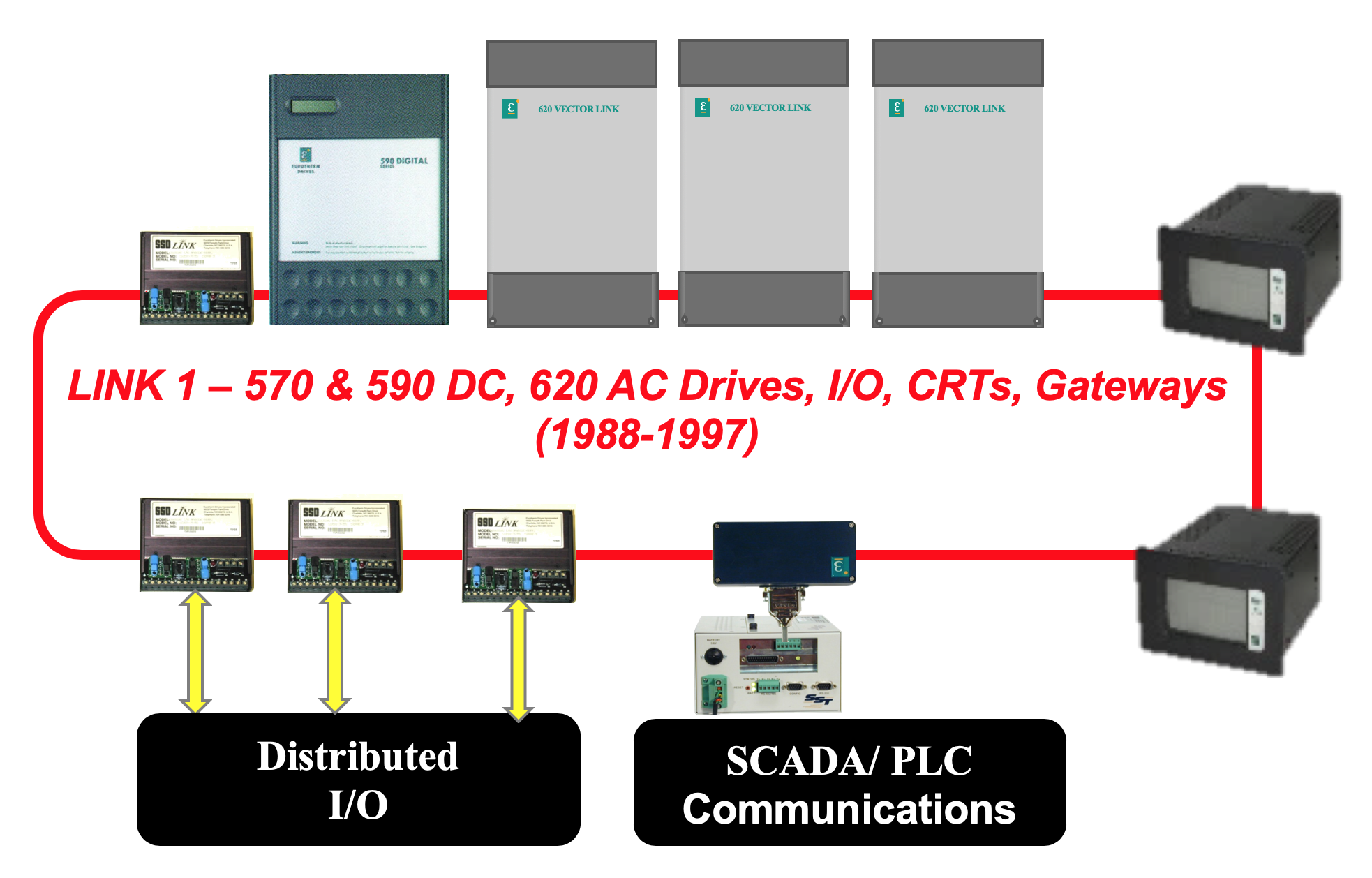
Drives core electronics “smarts” have evolved from analog to being almost exclusively digital microprocessor based. Multi-drive systems offer peer-to-peer deterministic speed reference communications as well as data communications to tell the outside world about the process. Motor speed feedbacks can be measured in parts per million for a single motor revolution when required for precision applications. Less precise applications, that historically required a motor mounted tachometer, today need no feedback device to mimic speed control performance. Drives incorporate Proportional-Integral-Derivative (PID) control, analog and digital inputs and outputs, and application specific control macros that eliminate the need for ancillary custom circuit boards of old. No need to custom design/trouble shoot systems with new control algorithms. Reduced system implementation risk is achieved by using drives with pre-engineered macros that are already proven for: non-linear acceleration/deceleration ramp rates, loadcell tension trim, dancer position control, draw control, load sharing, speed/position electronic line shaft, center-driven diameter compensated unwinds and winders and position camming. The internet has come to digital drive systems with browser based diagnostic capabilities that provide for secure remote location access to drive and process information for added support.

Drive Configuration Software
Measurement and Control Solutions can assist you in taking the complexity out of drive system specification, supply, commissioning and support. Our system proposals detail all items and their function so there is no ambiguity in the scope of supply, nor project responsibilities. All drive systems proposals are for completely engineered and documented control solutions to match the customer project needs.