Drive Systems & Components
We have sold and supported drive components and coordinated drive systems since our inception. Several important factors have not changed over that time. End-users still want cost effective drives that start-up in a timely fashion, are reliable in their operation, offer sound diagnostic tools to address operation problems and are fully supported for years (not months). We only sell drive products we know we can support and offer full installation, commissioning and lifetime trouble shooting and field support services.
We are an ideal resource for cross-referencing old components to currently supported products. We know drive products that work well from firsthand experience. Our drive component expertise has been gleaned from retrofitting hundreds of drives with new fully documented control replacements.
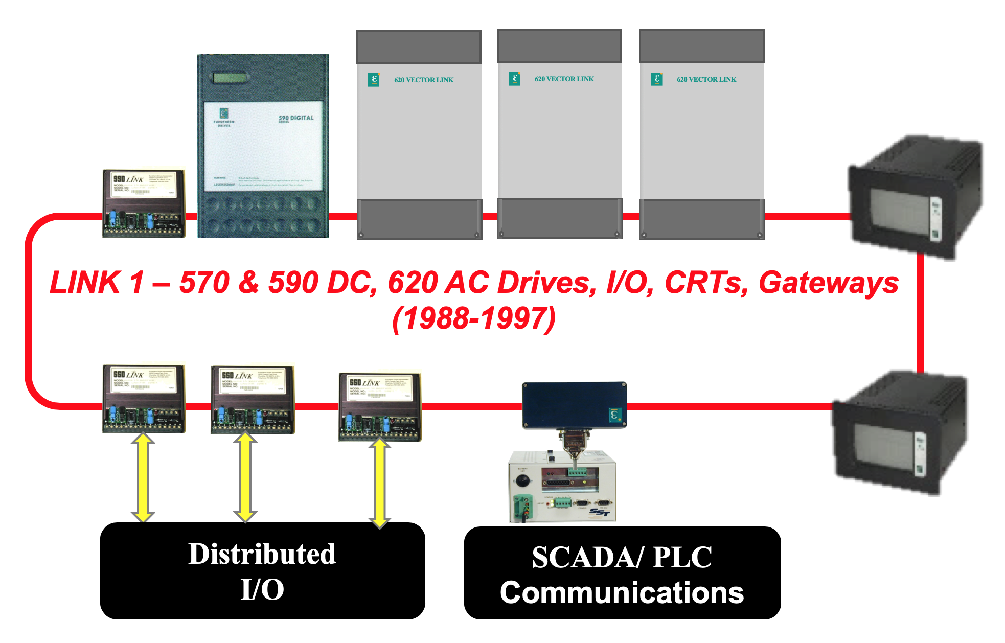
We have retrofitted most all major drive manufacturers systems but we are exceptionally well versed in Parker Hannifin (formerly known as Shackleton System Drives, SSD, Eurotherm Drives) products and systems. Our team offers technical support of existing lines and are expert in the retrofit of legacy Eurotherm Drives fiber-optic based LINK drive systems. We also source discontinued LINK components from past retrofit work and can counsel you on work around solutions where possible to help you with emergency issues.
Our system proposals detail all items and their function so there is no ambiguity in the scope of supply, nor project responsibilities. All drive systems proposals are for completely engineered and documented control solutions to match the customer project needs and expectations.
Please reach out to us to discuss your drive needs. We will be happy to organize a visit to your site to review your application’s needs.
COORDINATED Drive SYSTEMS
Retrofitting Legacy LINK Drive Systems
Discontinued LINK Component Parts
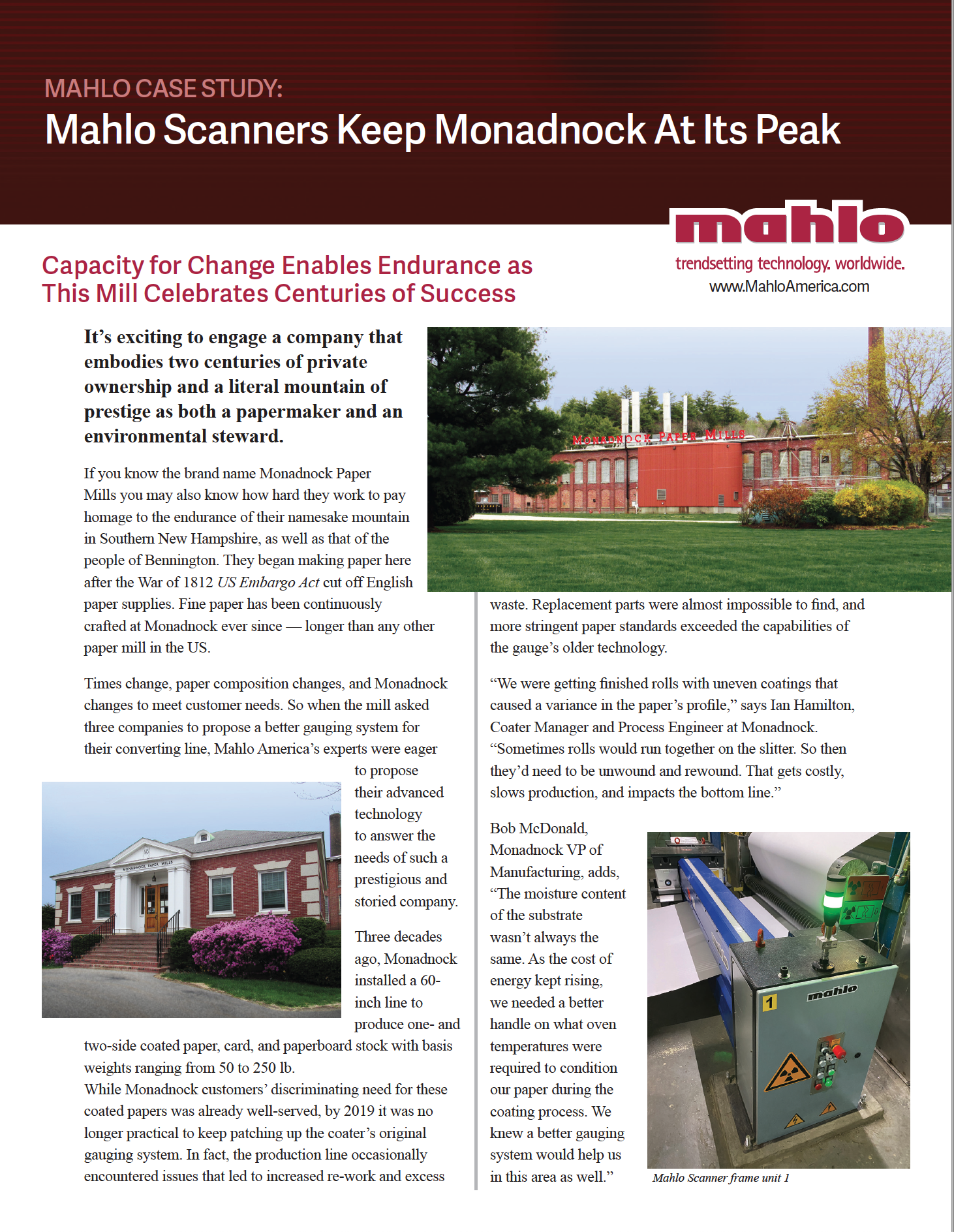
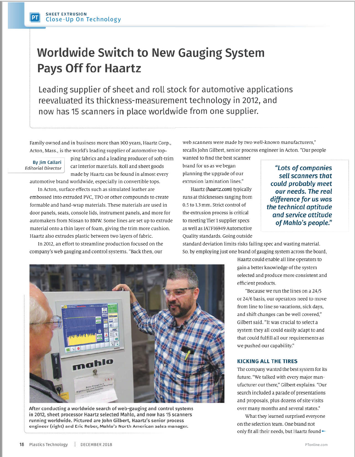
Web Gauging Systems
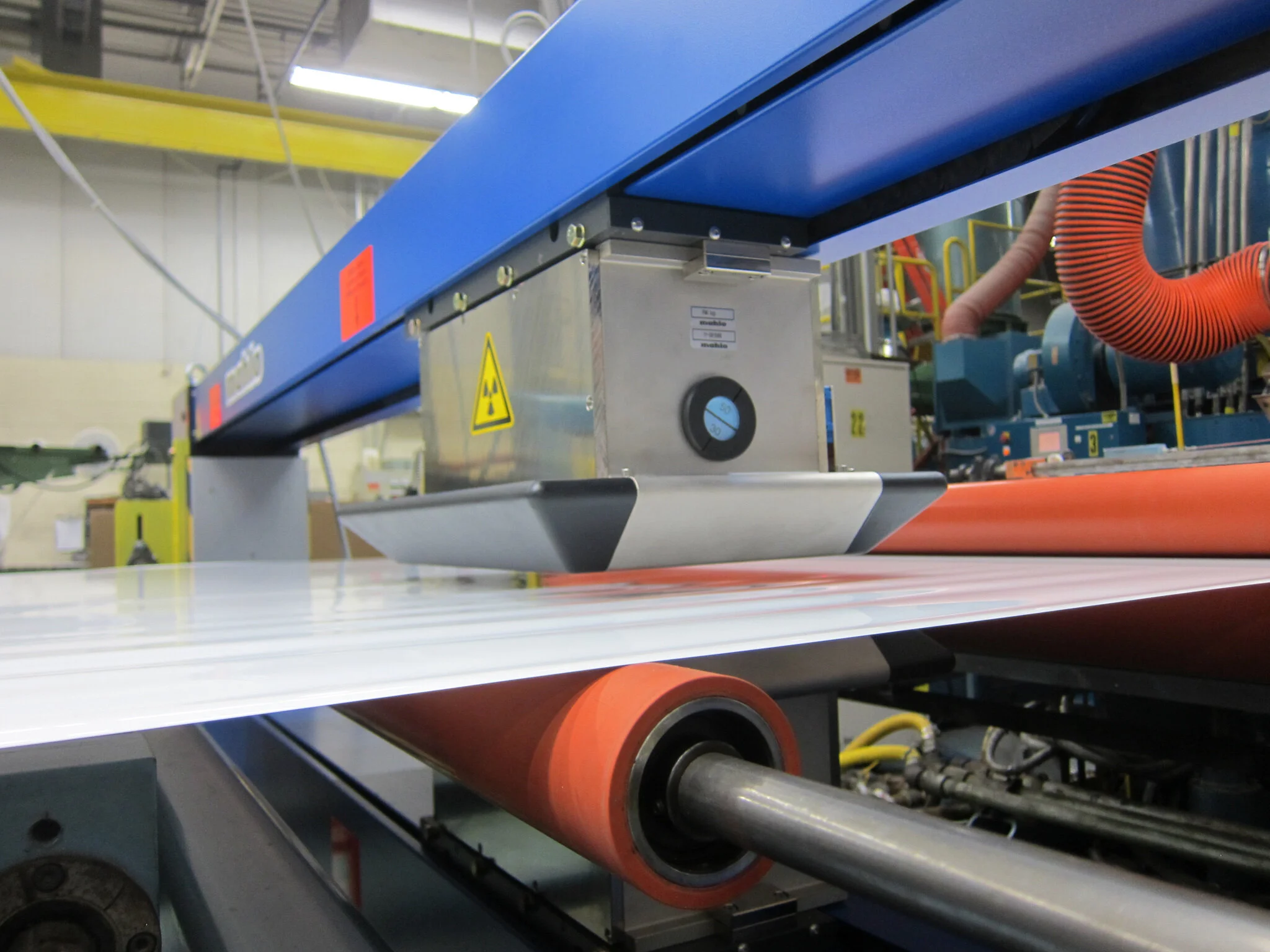
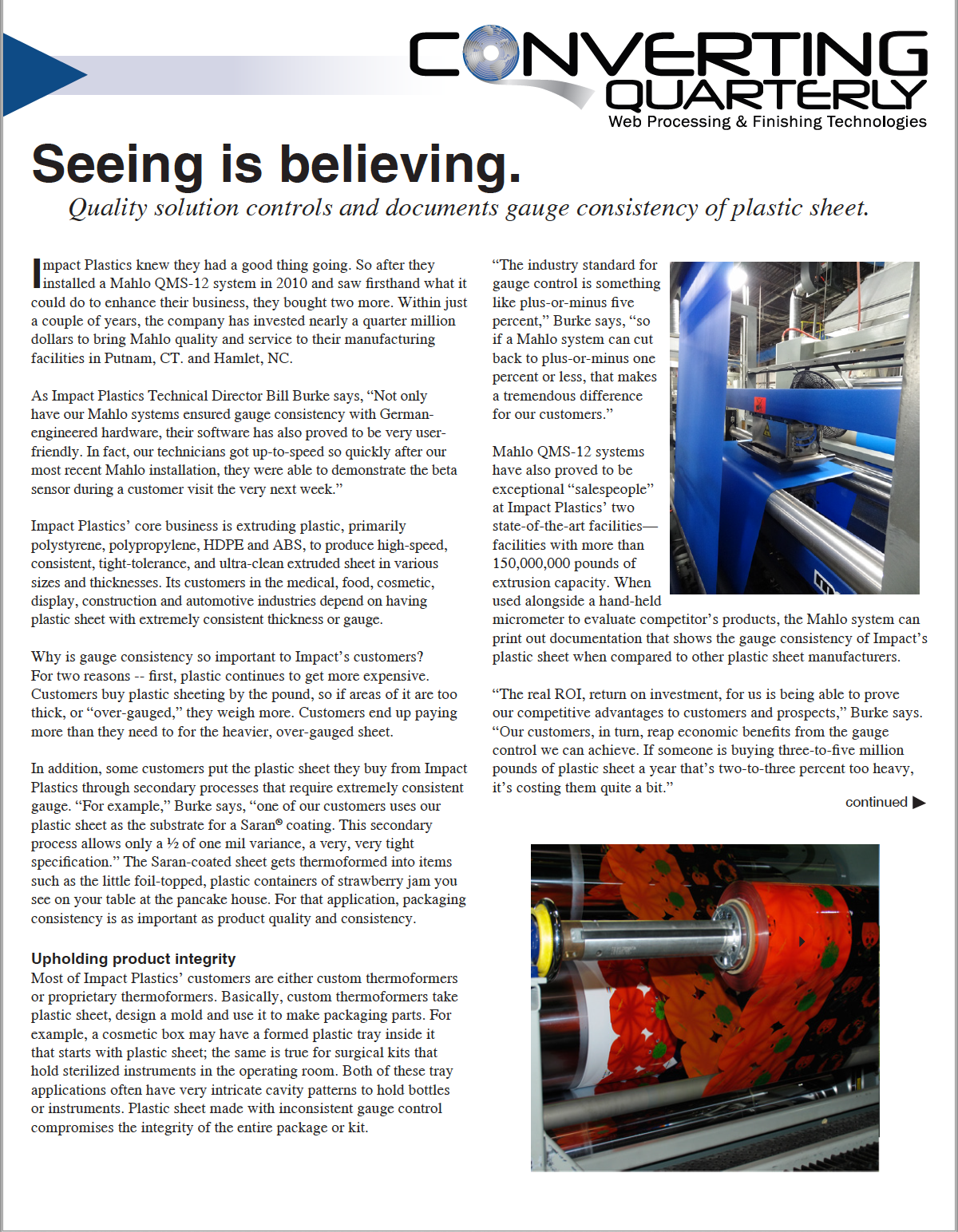
Product measurements are the most statistically accurate when obtained with an on-line gauging system solution. Extrusion, converting, nonwovens, textile, membrane, nanotechnology and paper processes are just some of the markets we support with scanning gauging solutions. Certified improvements in product changeover times, scrap reduction, roll or sheet quality, product uniformity, shift repeatability, labor efficiencies and reduced material costs are all typical areas for returns on a gauging capital investment.
Measurement sensor technology can incorporate nuclear, non-nuclear, laser, infrared, and X-Ray options. The best choice(s) depends upon the customer’s specific product type(s) and measurement needs. Gross product or net coat weight, thickness, density and moisture are the most commonly gauged measurements but other measurement parameters are also possible.
Once a valid measurement is obtained, control can be applied to optimize the process and shift-to-shift product consistency. Automatic profile control can be applied through the use of adjustable die, headbox or roll height. Machine direction control can be provided by adjusting line, pump, screw speeds or other areas where measurement feedback can affect positive control results. Target shift management can be applied to optimize your material savings while ensuring you are delivering in specification product.
Data handshakes to PLCs, SCADA and other facility data systems are straight-forward to implement to enable features like global recipe control for various product types, early alarming for out of specification products, quality data analysis/improvements and certified history for each roll, slit roll or sheet produced.
MCS is proud to partner with Mahlo America for web gauging solutions. Mahlo has proven to us to be the best value in the web gauging market today especially when you consider: corporate longevity (established in 1945), commitment to research and development, breadth of highly repeatable sensors, precision control offerings, robustness of scanner builds and Mahlo’s commitment to lifetime system service and support.
Please reach out to us to discuss your application and we will organize a complementary lab trial to run your product and prove out the measurements that are of value to you.
Automatic Web Inspection Systems
The human eye and process trained brain can combine to make an extremely powerful web inspection system. However, it has been proven in multiple industrial studies, that even experienced operations personnel become fatigued and are susceptible to distraction when asked to make historic logs of mundane/repetitive inspection tasks. The job of manual inspection and flagging of products for defects has proven to be prone to frequent errors regardless of its crucial importance in a final product’s quality certification. We provide automatic on-line web inspection systems that continuously inspect 100% of a moving material. Our automatic on-line inspection experience applies to paper, film, coating, non-woven, textile, extrusion, battery, membrane, metals, glass and other continuous web applications.
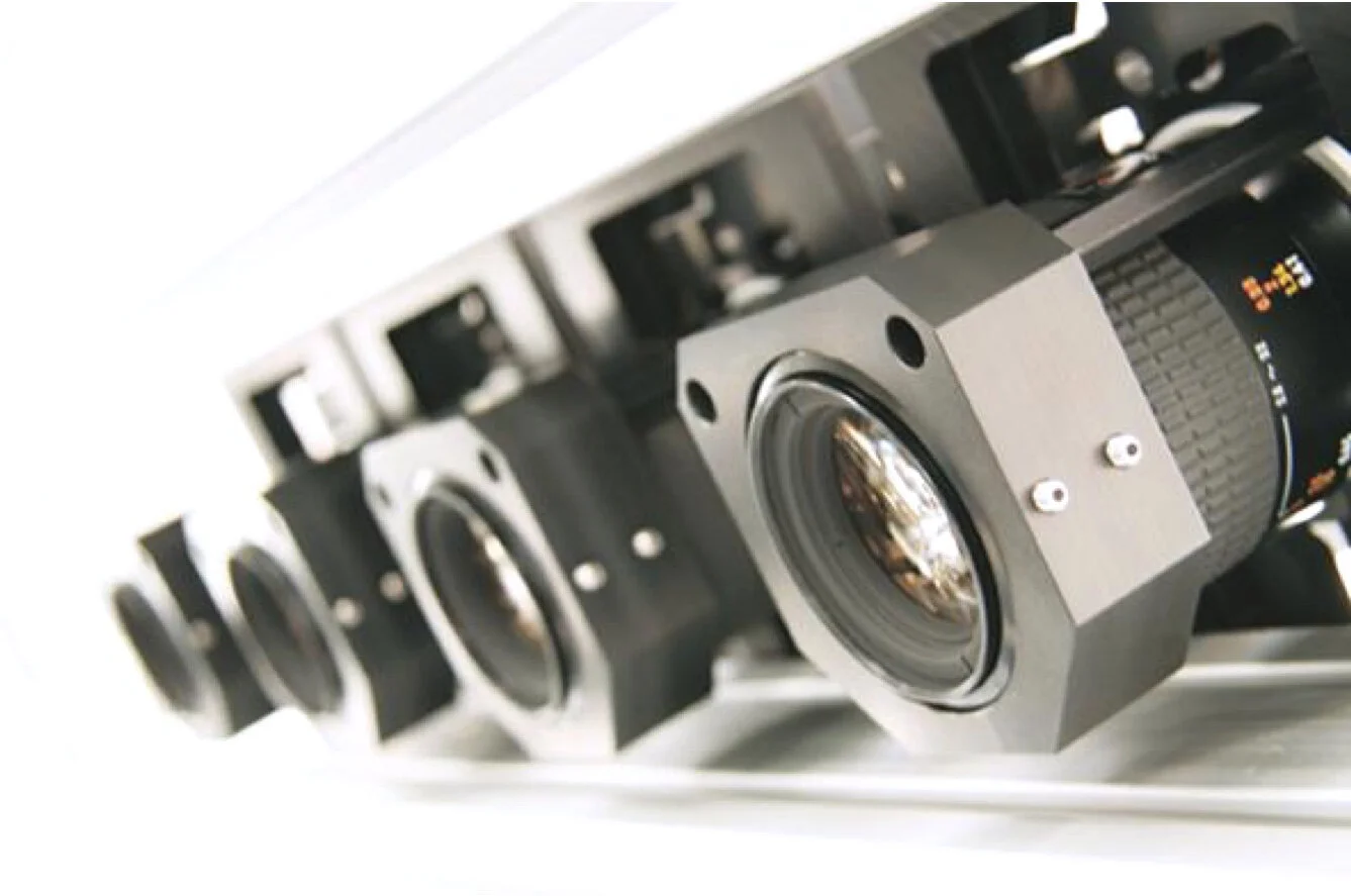
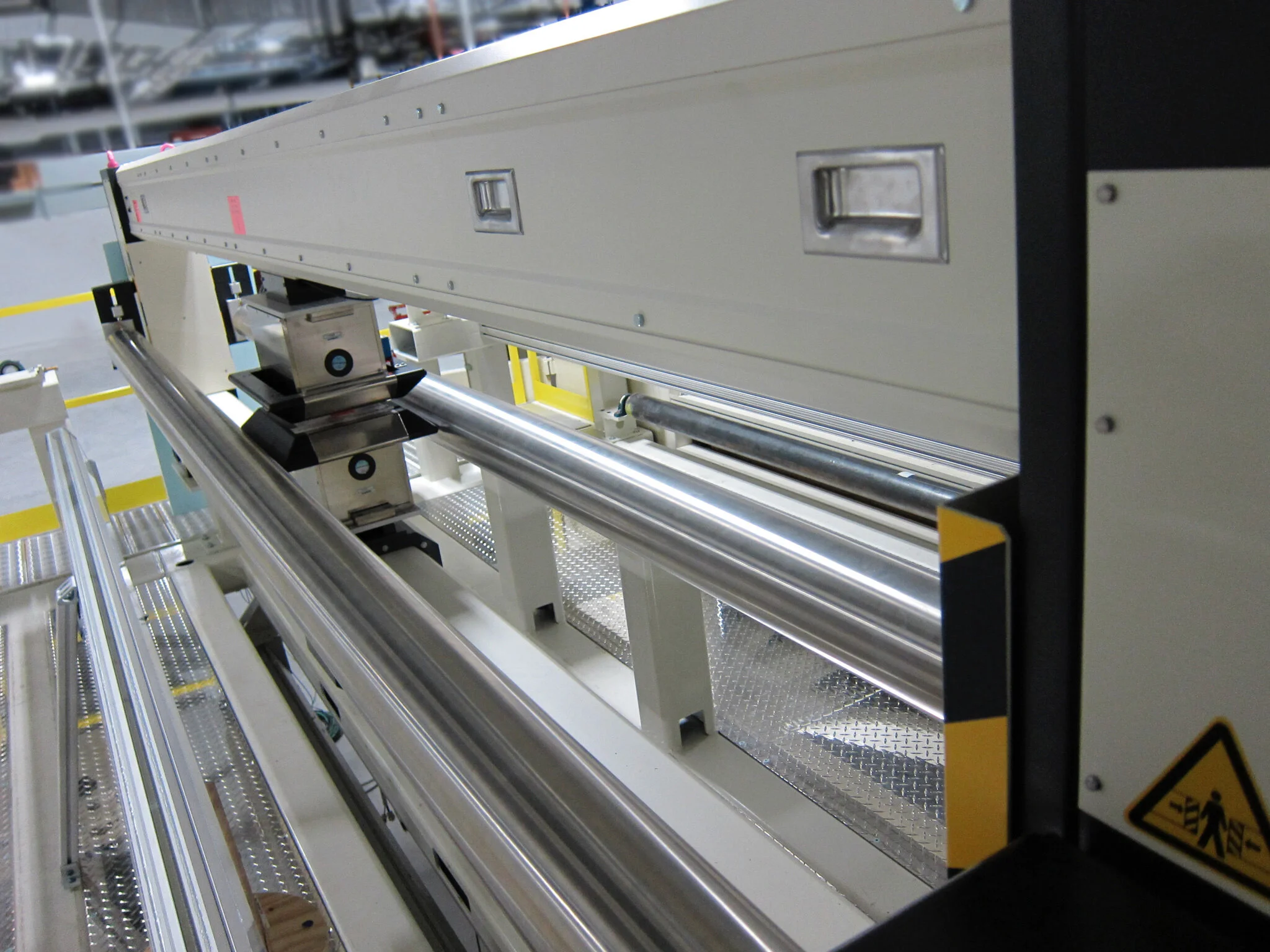
Historically, web inspection systems have used laser, cameras or hybrid combinations of sensors as their core optics technologies. Today, camera web inspection has emerged as the default solution in all but the most specialized of applications. Cameras success for web inspection applications are due to their continuously improving price performance ratio relative to other technologies – especially when the total cost of ownership is considered.
Web inspection solutions use high-speed parallel smart camera topology to stream defect data to a central workstation to display/sort mapped images and statistics. For example, line scan camera systems are available that can provide throughput of faster than a gigapixel/second/camera. Line scan camera systems provide flexible and modular solutions in both their optical and mechanical layouts. Therefore, pixel resolutions are not fixed. Rather, they can vary based on the inspected material width, number of cameras used, and the speed of the material. While pixel resolutions of 10 microns per pixel or better are feasible, most applications actually require far lower resolutions, in the range of 50-200 microns per pixel. Line scan cameras can also readily inspect materials running at 1000 mpm (3281 fpm) or faster. The modular nature of line scan camera systems means virtually any width of material can be inspected with typical widths ranging from 50 mm (2 inches) to 4 meters (13 feet) with even wider material possible. Defect information is displayed in a convenient, ergonomic manner that is easily understood by both operator and engineering personnel. Classifiers are employed that discern and segregate defects such as holes, streaks, scratches, wrinkles, edge tears, inclusions, gels, particulates, bugs, dirt, oil, watermarks, and inconsistent formations. Defect data is readily networked, stored and evaluated in databases (e.g. SQL) by number of defects per area and/or severity levels for further production and quality analysis to provide product certification records. Defect data can also be segregated by cross web position relative to multiple slit lanes or by web direction lengths when making sheet products. Control charting options to support quality programs are also readily available. Defects can be traced by their repeat length that correlate to specific roll circumferences within the production line to assist operators with early warnings of manufacturing issues. Web marking options are available to identify defect location in a roll or sheet for future product disposition/yield analysis.
We will always attempt to offer you preliminary price range for a web inspection system after an initial discussion regarding the specifics of your application. Preliminary web inspection criteria discussed may include: web widths, line speeds, product types, defect types and level of importance, defect sizes, defect contrasts, operating environment, single or dual side inspection, marking systems and data links. For applications with a wide range of product types and/or where detection of defects with subtle optical characteristics are required, we will ask you to provide a representative defect sample set before we develop a final proposal. We will provide a complementary application report of this defect sample set that will serve to qualify and quantify inspection results for each defect type. This report will form the basis of our commercial commitment to you. Our goal is always to provide a final system deliverable that meets your expectations for results. We look forward to assisting you with your next web inspection need.
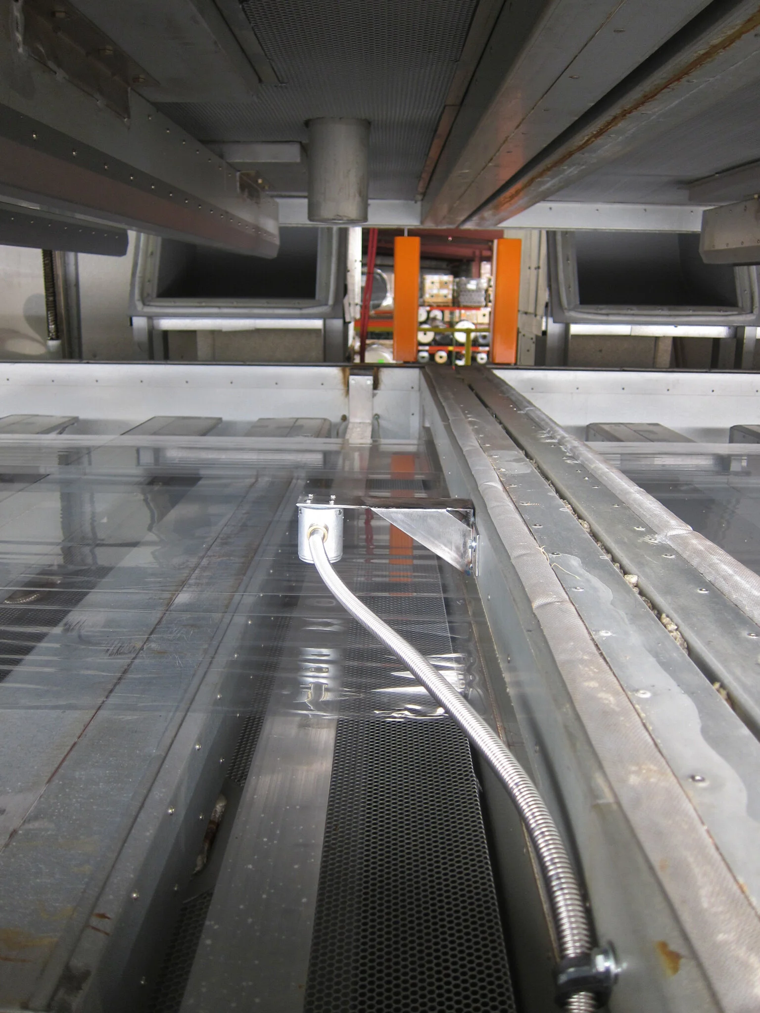
Measuring Web Temperature Inside Ovens
Precise, repeatable measurement and control of material temperature while in an oven can offer marked improvement in a line’s productivity, energy costs and product quality. In the drying process of solvent and aqueous coatings on films, papers, textiles and other webs, material may span well over 100 feet and remain in the oven over several minutes. Ensuring that the web temperature is in specification during this time can be the difference between making high quality product or scrap. Harsh, high temperature oven environments require robust sensor designs. Please reach out to us for the supply of oven web temperature measurement sensors that feature:

Robust, intrinsically safe, non-contact, sensor design that is suitable for use in EXP (Solvent) or Non-EXP (Aqueous) environments
Two sensor designs:
Standard Temperature (ST) design for webs from 0-250°C (32-482°F)
High Temperature (HT) design for webs from 0-426°C (32-800°F)
Measurement is insensitive to different material colors and clarity. The measuring principle is based on exchange of thermal radiation between the material to be measured and the temperature sensor’s surface. This is not an IR device – excellent measurements on clear films.
Real time response
Resistive to soiling
No calibration required after initial set up
Insensitive to condensation
Typical measurement accuracy: +/- 1%
Measurement Signals: 0/4-20mA or RS485 Serial Communications (Modbus)
Multiple sensors are normally fitted along the length of the oven and/or several sensors are applied in a single cross direction row for left – center – right web temperatures monitoring
Sensor Stand-Off Distance to Material: 20-120 mm (0.8-4.7”)
Circular temperature measurement area on material is based upon the material stand-off distance from sensor:
140 mm (5.5”) measurement diameter at 20 mm (0.8”) stand-off distance from web
300 mm (11.8”) measurement diameter at 60 mm (2.4”) optimal stand-off distance from web
550 mm (19.7”) measurement diameter at 120 mm (4.7”) distance stand-off distance from web
Straight forward installation - Sensor cables, mounting brackets, oven grommets and sensor interface enclosure are included as necessary with all quotes